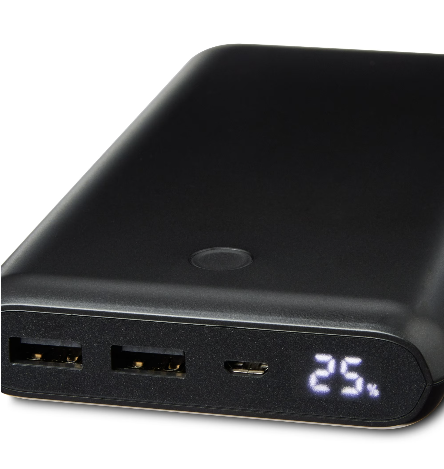
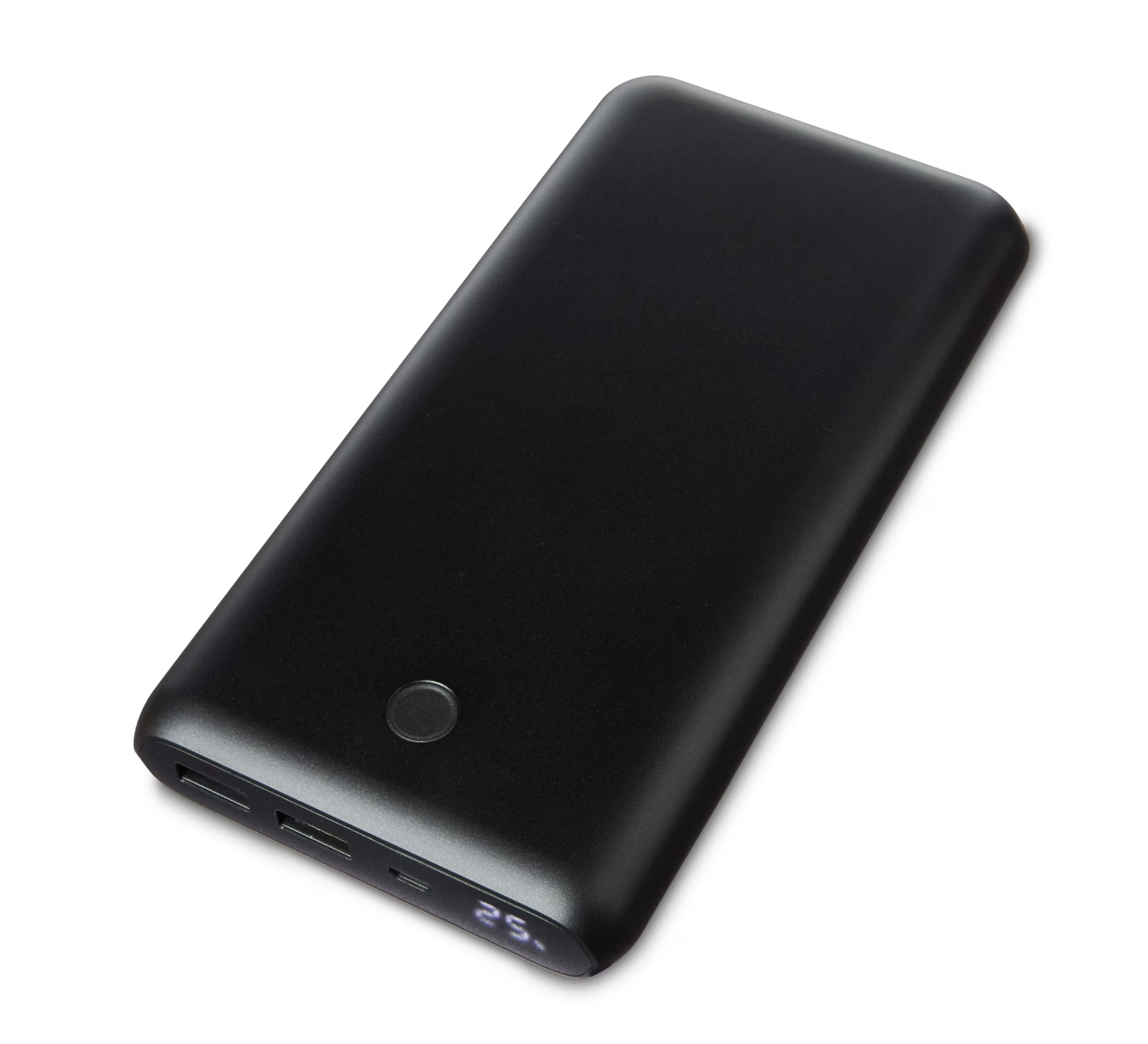
A while back I bought one of these battery packs from Walmart. It was total junk. It was advertised as 20,000mAh but the pack had a sneaky “Rated for 12,000mAh” marked on the case. The thing lost all charge capacity within a year and would never charge over 15%. Before tossing it out I figured I could pull it apart and see how it worked. One part that caught my eye was the charge indicator, a 5-pin segment LED display.
Ive worked with 7-segment displays countless times. Most modules use a common cathode/anode setup, where one pin is common and every other pin lights up a specific segment. A single digit has 8 pins (7 for each segment, 1 for the common). Multiple digits can be multiplexed to form a larger display.
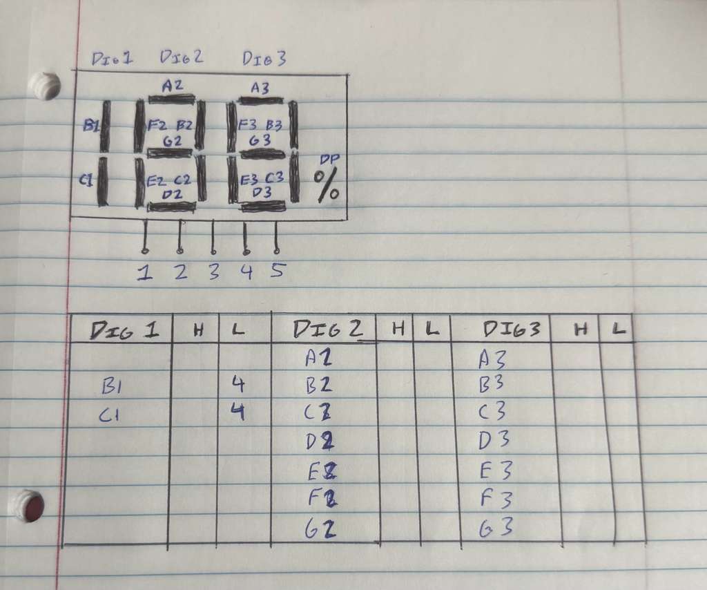
This display was interesting as it only had 2 full digits, 1 “half digit” which could only display 0 or 1, and a percent indicator. More importantly, it only had 5 IO pins. The model number KL1508CW yielded no results online which was expected for such an obscure part. The manufacturers were probably trying to squeeze every penny out of their designs so these displays are often found in cheap battery packs and disposable vapes.
Charlieplexing
The lack of IO pins was a clear indicator that this display is charlieplexed. Charlieplexing is a classic method of driving numerous LEDs with minimal IO pins. We know that a standard 7-segment display needs 8 pins to work. Now if we are engineering a mass produced, dirt cheap system, we want to use as little IO as possible.
Take a single LED with its anode connected to an IO pin and its cathode connected to GND. With 1 pin, we can drive 1 LED (duh).
Now add a second LED in reverse, and replace the GND with an IO pin. By setting X1 HIGH and X2 LOW, we drive LED1. Setting X1 LOW and X2 HIGH drives LED2. Setting both IO LOW turns both LEDs off. Now we can drive 2 LEDs with 2 IO pins.
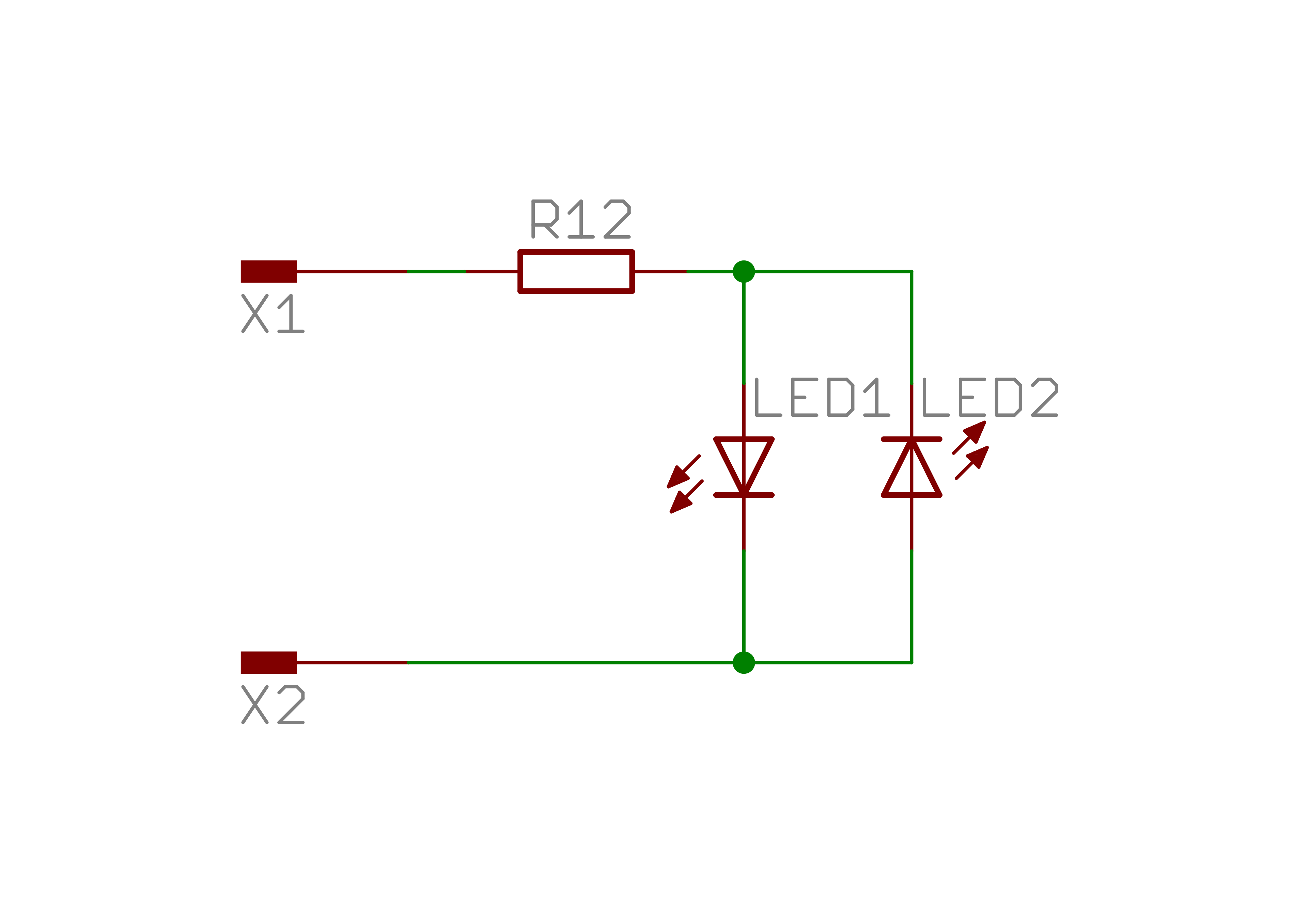
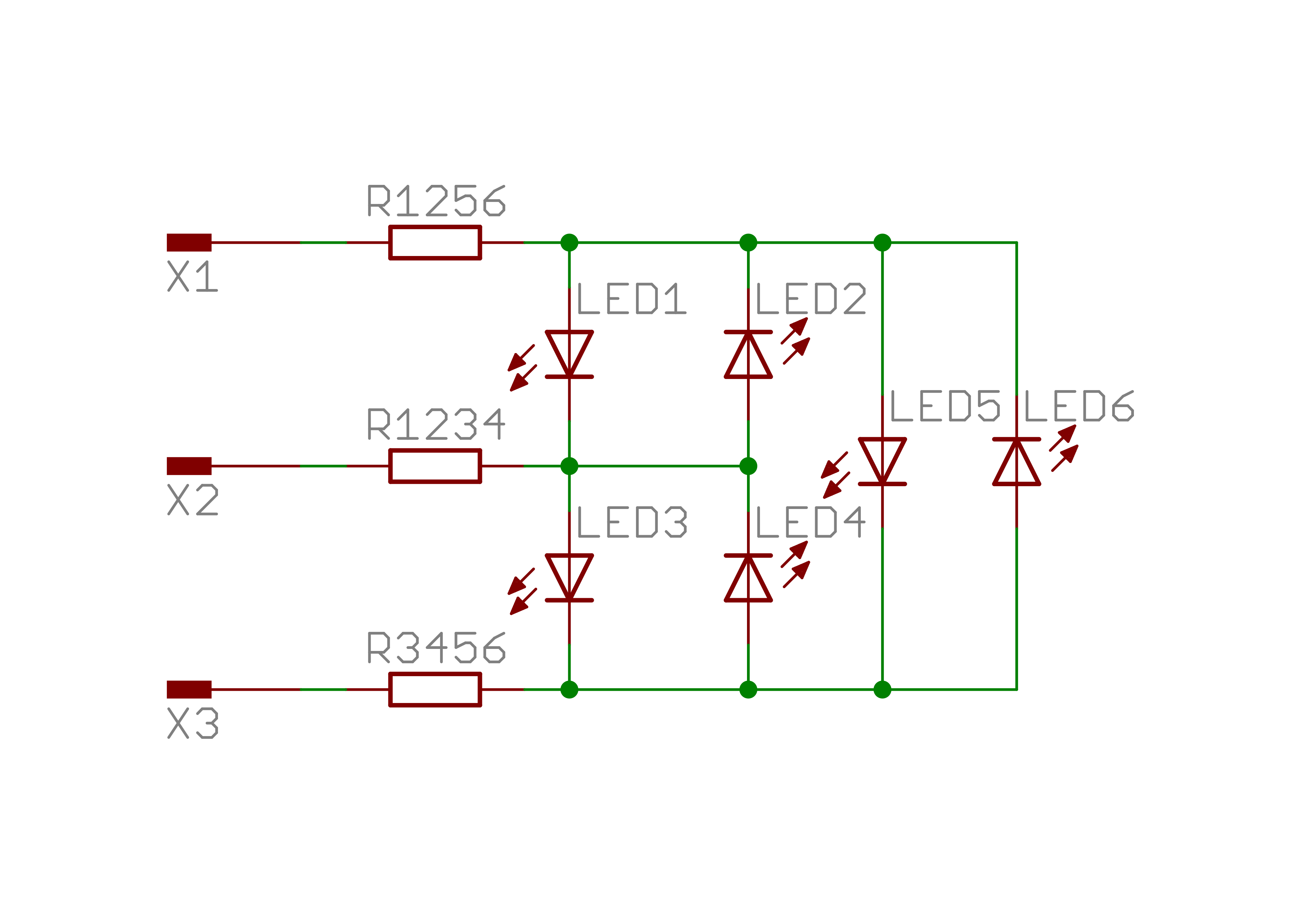
Of course this isnt that special, we still need 2 IOs for 2 LEDs. Where this becomes interesting is when we increase the number of IOs. With 3 pins, we can drive 6 LEDs!
What makes this work is the ability to tri-state our IO pins. By setting an IO to High-Z (high impedance), we effectively disconnect it from the circuit. The other IOs can then be set HIGH/LOW to drive individual LEDs.
We can take this further by adding more IOs as needed. The formula for determining the number of LEDs controllable is $n^2-n$, so 4 pins can control 12 LEDs, 5 can control 20, and 20 can control 380! While an old method of driving many LEDs, Charlieplexing is still used in appliance displays, flat-panel screens, and digital billboards.
Display Pinout
Probing the display pins with a multimeter confirmed that the LEDs are Charlieplexed. There are 17 total segments (7 segments for each of the 2 digits, 2 segments for the half-digit, and a percent indicator). As we saw earlier, 5 IO is the minimum pin number to drive these many pins.
I labeled each segment and mapped which 2 pins needed to be driven HIGH/LOW to activate them. The next step is to determine the pin assignments for displaying digits.
Mapping Segments to Digits
As the end goal of this project is to create a reusable Arduino library, its important to organize the mapping in a modular fashion. The approach I chose was on a digit-by-digit basis:
- Programmer passes 3-digit number into a display function
- Display splits number into individual digits
- Segment display is driven 1 digit at a time
With traditional Charlieplexing it is assumed that only 1 segment can be turned on at any point. That is often not the case. By taking advantage of pin assignments and the needed segments for specific numbers I was able to drive up to 4 segments at a time!
I first figured out the segments needed to display each number from 0-9. For example, displaying “1” requires segment B and C to be lit. According to my mapping from earlier, for Digit 1 (the “half digit”) setting pins 2 and 3 HIGH and pin 4 LOW turns on segments B and C.
Storing The Data
Continuing with this process, it was clear that it was not possible to display a full number in 1 cycle. I solved this by looping through several cycles for each number. Each digit shall store a lookup table of numbers (0-9), where each entry will be a 4-length array of cycles to run through. The reason I chose 4 is that it was the minimum number of cycles needed to display every number on every digit.
The next step was finding a clean way to store the needed data in these lookup tables. As the device has 5 tri-state IO pins and 1 needs to be held LOW, I went with this scheme:
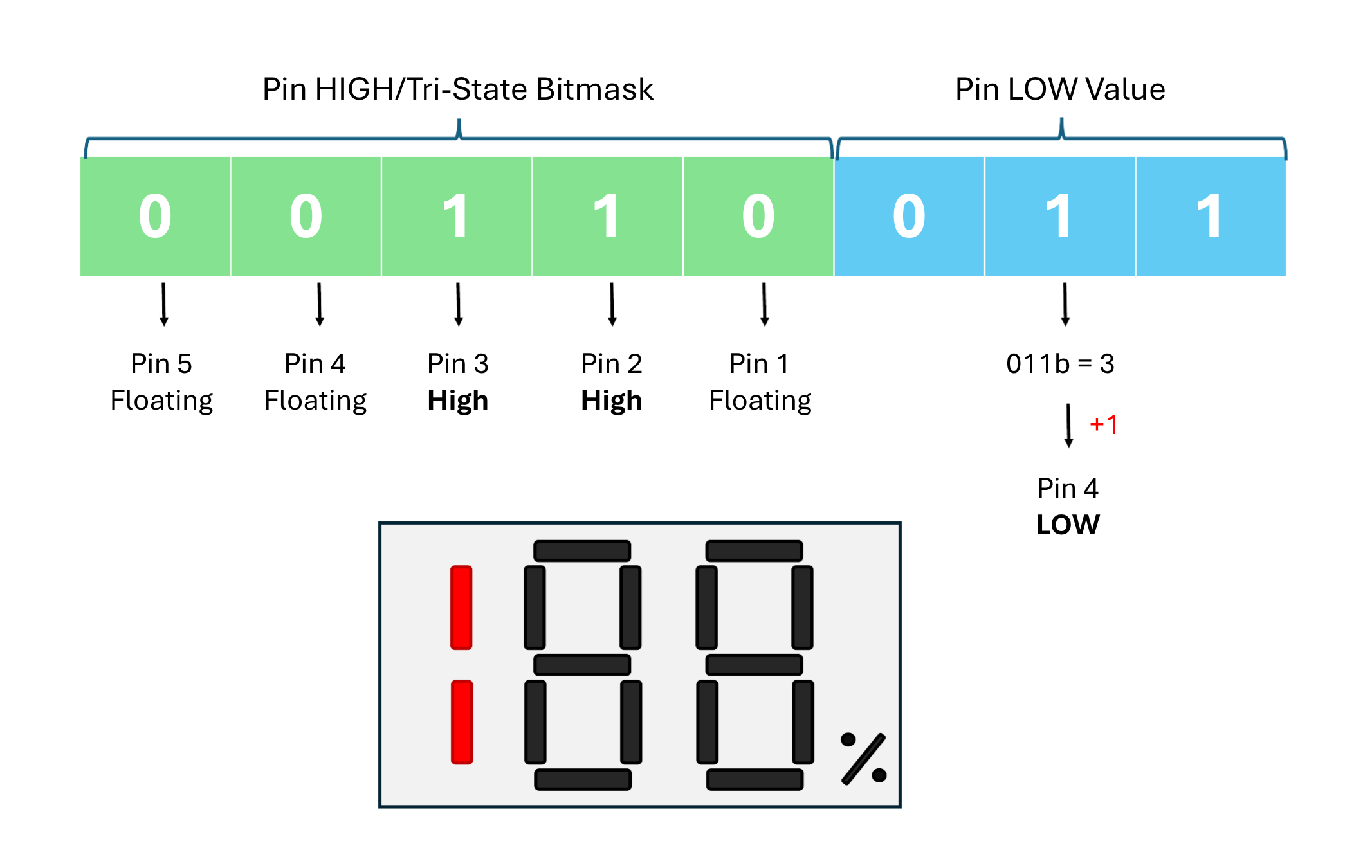
Each cycle byte packs the full pin state into 8 bits. The lower 3 bits hold the index (0–4) of the single pin to drive LOW. The upper 5 bits are a bitmask, a set bit means that pin is driven HIGH. Any pin not referenced in either field is tri-stated (floating). For example, 0b11100001 drives pin 1 LOW (001) and pins 2, 3, 4 HIGH (11100); pin 0 floats. driveSegment() extracts both fields with two operations: low_pin_idx = segment & 0b00000111 and high_pin_idxs = segment >> 3.
This is particularly elegant as it stores a full cycle in a single byte, making it cleanly fit into 8-bit architectures.
The Code
Now that we have the general dataflow and structure schema, we can start implementing the driver code. This can be cleanly implemented using a C++ class.
class KL1508CW {
public:
  KL1508CW(const uint8_t pins[5]);  // Constructor

  void displayNumber(uint8_t number, bool percent);   // Set a number to display (1–199)
  void tick();                          // Call frequently in loop() to refresh display

private:
  uint8_t _pins[5];
  uint8_t _segments[4][4];              // Current frame data for each digit and percent
  uint8_t _phase = 0;                   // Scan phase (0–3)

  void driveSegment(uint8_t segment);
  void extractDigits(uint8_t number, uint8_t &hundreds, uint8_t &tens, uint8_t &ones);
};
The _pins array contains the actual IO pins to be controlled and is initialized on startup.
The _segments array is our framebuffer. It contains 4 phases per digit/percent.
The _phase variable tracks the current cycle we are at. The driver rapidly cycles through the 4 phases of a digit, then moves onto the next. This nested setup is repeated continuously.
Lookup tables
How does Charlieplexing show a fully-lit 7-segment digit when it can only energize a few segments at once? It doesn’t, it cycles through phases so fast that persistence of vision fills in the rest.
Each lookup table entry is 4 bytes: one byte per phase. A single tick() call drives one phase of one digit. The driver exhausts all 4 phases of the current digit, then advances to the next (hundreds, tens, ones, percent), then loops back. At 500 μs per call, one digit’s 4-phase cycle completes in 2 ms. A full pass over all four display elements takes 8 ms (125 Hz), well above the flicker threshold.
// ----- Segment lookup tables
byte percent_vals[2][4] = {{0b00000000, 0b00000000, 0b00000000, 0b00000000}, // empty
                          {0b00010100, 0b00010100, 0b00010100, 0b00010100},  // %
                          };

byte dig_1_vals[2][4] = {{0b00000000, 0b00000000, 0b00000000, 0b00000000}, // 0 (empty)
                          {0b00110011, 0b00110011, 0b00110011, 0b00110011}, // 1
                          };

byte dig_2_vals[10][4] = {{0b11100001, 0b11010010, 0b11100001, 0b11010010}, // 0
                          {0b00100001, 0b01000010, 0b00100001, 0b01000010}, // 1
                          {0b11100001, 0b00010010, 0b10000011, 0b10000011}, // 2
                          {0b01100001, 0b01010010, 0b10000011, 0b10000011}, // 3
                          {0b00100001, 0b11000010, 0b10000011, 0b10000011}, // 4
                          {0b01000001, 0b11010010, 0b10000011, 0b10000011}, // 5
                          {0b11000001, 0b11010010, 0b10000011, 0b10000011}, // 6
                          {0b00100001, 0b01010010, 0b00100001, 0b01010010}, // 7
                          {0b11100001, 0b11010010, 0b10000011, 0b10000011}, // 8
                          {0b01100001, 0b11010010, 0b10000011, 0b10000011}, // 9
                          };

byte dig_3_vals[10][4] = {{0b01110000, 0b00001001, 0b00001010, 0b00001011}, // 0
                          {0b00010000, 0b00001010, 0b00010000, 0b00001010}, // 1
                          {0b10110000, 0b00001001, 0b00001011, 0b00001011}, // 2
                          {0b10110000, 0b00001001, 0b00001010, 0b00001010}, // 3
                          {0b11010000, 0b00001010, 0b11010000, 0b00001010}, // 4
                          {0b11100000, 0b00001001, 0b00001010, 0b00001010}, // 5
                          {0b11100000, 0b00001001, 0b00001010, 0b00001011}, // 6
                          {0b00010000, 0b00001001, 0b00001010, 0b00001010}, // 7
                          {0b11110000, 0b00001001, 0b00001010, 0b00001011}, // 8
                          {0b11110000, 0b00001001, 0b00001010, 0b00001010}, // 9
                          };
I created 4 lookup tables (1 per digit and 1 for the percent sign).
Digit Extraction
This function takes a 3 digit number and extracts each individual digit. It validates the number to ensure it is equal to or less than 199 (the maximum displayable value). Note that upper-bound validation isnt needed as an unsigned 8-bit integer can only go up to 255.
void KL1508CW::extractDigits(uint8_t number, uint8_t &hundreds, uint8_t &tens, uint8_t &ones) {
  if (number > 199) number = 199;
  hundreds = number / 100;
  tens = (number % 100) / 10;
  ones = number % 10;
}
Display Number
This is the main function accessible to the library user. It extracts the individual digits, pulls the necessary cycle rows from the lookup tables and assigns them to the _segments buffer.
void KL1508CW::displayNumber(uint8_t number, bool percent) {
  uint8_t h, t, o;
  extractDigits(number, h, t, o);

  for (int i = 0; i < 4; i++) {
    _segments[0][i] = dig_1_vals[h][i];
    _segments[1][i] = dig_2_vals[t][i];
    _segments[2][i] = dig_3_vals[o][i];
    _segments[3][i] = percent_vals[percent][i];
  }
}
Segment Driver
At this point we have collected the requested number from the user, split it into individual digits, and constructed the framebuffer to be displayed. This function drives a segment (a single phase of a single digit). It first extracts the IO to set LOW and the remaining pin bitmasks. In this bitmask, any set bit has its pin set HIGH and any reset bit (that isnt the LOW pin) has its pin tri-stated.
void KL1508CW::driveSegment(uint8_t segment) {
  const uint8_t low_pin_idx = segment & 0b00000111;
  const uint8_t high_pin_idxs = segment >> 3;

  for (int i = 0; i < 5; ++i) {
    if (i == low_pin_idx) {
      pinMode(_pins[i], OUTPUT);
      digitalWrite(_pins[i], LOW);
    } else if (high_pin_idxs & (1 << i)) {
      pinMode(_pins[i], OUTPUT);
      digitalWrite(_pins[i], HIGH);
    } else {
      pinMode(_pins[i], INPUT);  // High-Z
    }
  }
}
To cycle through phases, a tick() function is used. This function shall be placed in the loop() section and be called continuously. Calling tick() cycles the phases enabling display of each number. Once all phases for a digit is exhausted, the driver moves on to the next digit.
void KL1508CW::tick() {
  static uint8_t digit = 0;

  driveSegment(_segments[digit][(_phase++) % 4]);

  if (_phase >= 4) {
    _phase = 0;
    digit = (digit + 1) % 4;
  }

  delayMicroseconds(500);  // Tune this to reduce flicker
}
Putting It All Together
With the driver complete, it was just a matter of wiring the display up to a microcontroller, writing some basic example code, and testing it out!
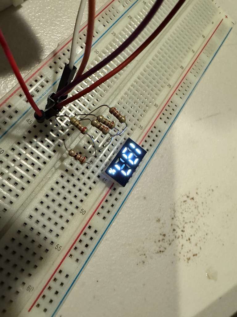
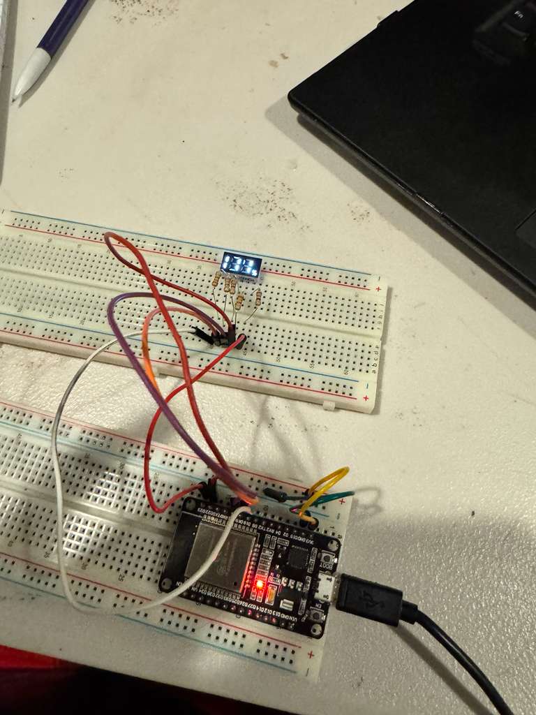
I created this simple example sketch that rapidly sweeps through all the numbers. After cleaning out a few bugs, the driver was ready!
#include <KL1508CW.h>

const uint8_t displayPins[5] = {18, 19, 21, 22, 23}; // Change these to match your pins
KL1508CW display(displayPins);

uint16_t currentValue = 1;
unsigned long lastUpdate = 0;
const unsigned long updateInterval = 250; // Change number every 100ms

void setup() {
  display.displayNumber(currentValue, true);
}

void loop() {
  // Continuously refresh display
  display.tick();

  // Change number based on time
  unsigned long now = millis();
  if (now - lastUpdate >= updateInterval) {
    lastUpdate = now;

    currentValue++;
    if (currentValue > 199) currentValue = 1;

    display.displayNumber(currentValue, true);
  }
}
Conclusion
I used this display for a tank meter in my garage, and it has been working flawlesly so far. I love bringing new life into these “junk” parts, especially if I can learn something new along the way.
While it is very unlikely that someone else will ever need to use one of these displays, I figured that it is worthwhile to make a general Arduino library for it. I hope you found this dive into Charlieplexing as interesting as I did!