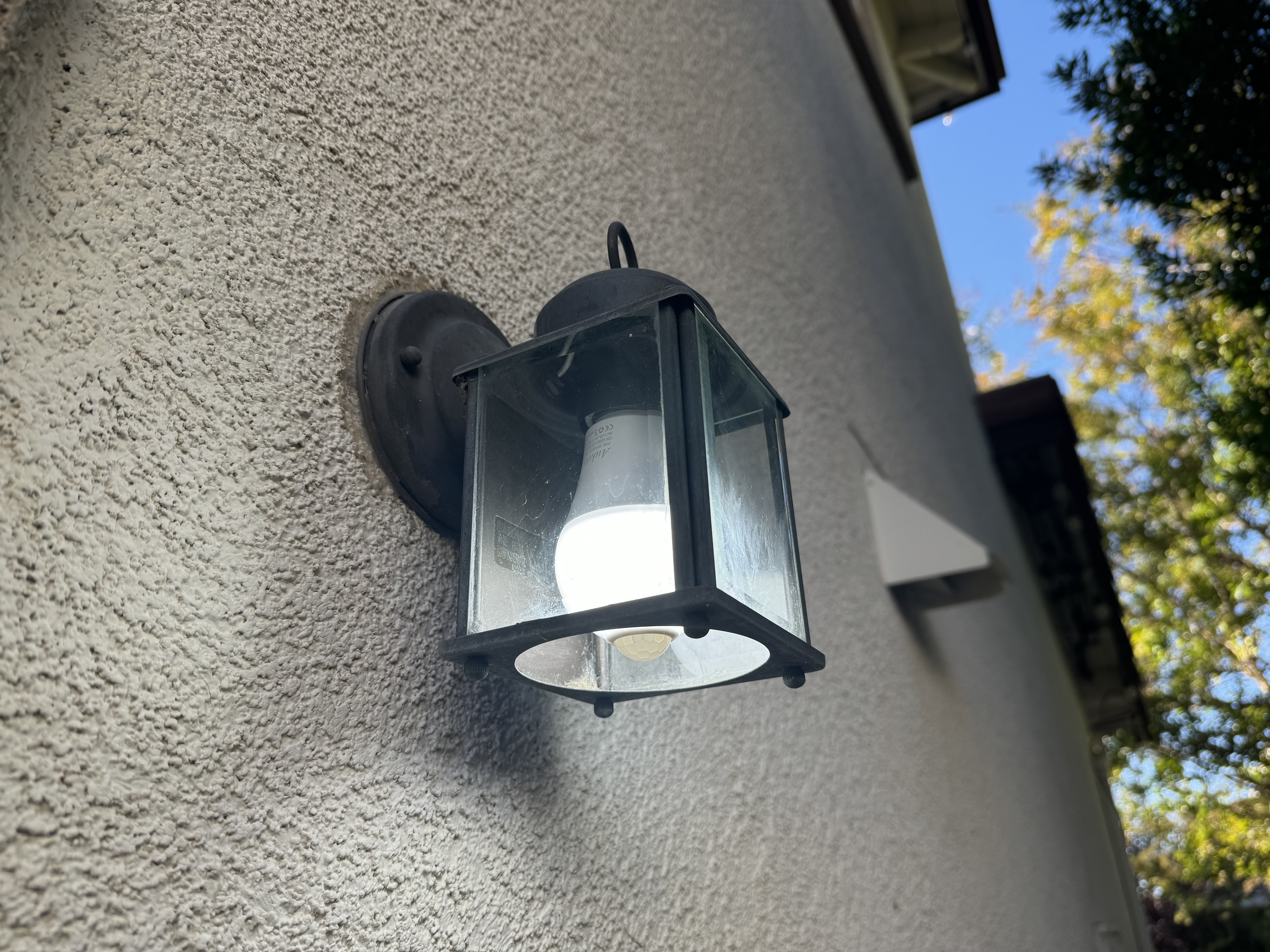
I have a couple motion-activated LEDs outside my garage near the sideyard. On top of spooking the racoons, these have been a lifesaver when im taking out the garbage in the evening and dont have a hand free to hit the lightswitch. My biggest gripe with them was that they turn off way too soon! They shut off within 30s of being triggered, often leaving me in the dark with a large trash bag in my hands.
I figured that reverse engineering how these bulbs worked would be a interesting weekend exercise. Turns out that theres alot of really cool engineering under the hood.
Cracking The Bulb Open
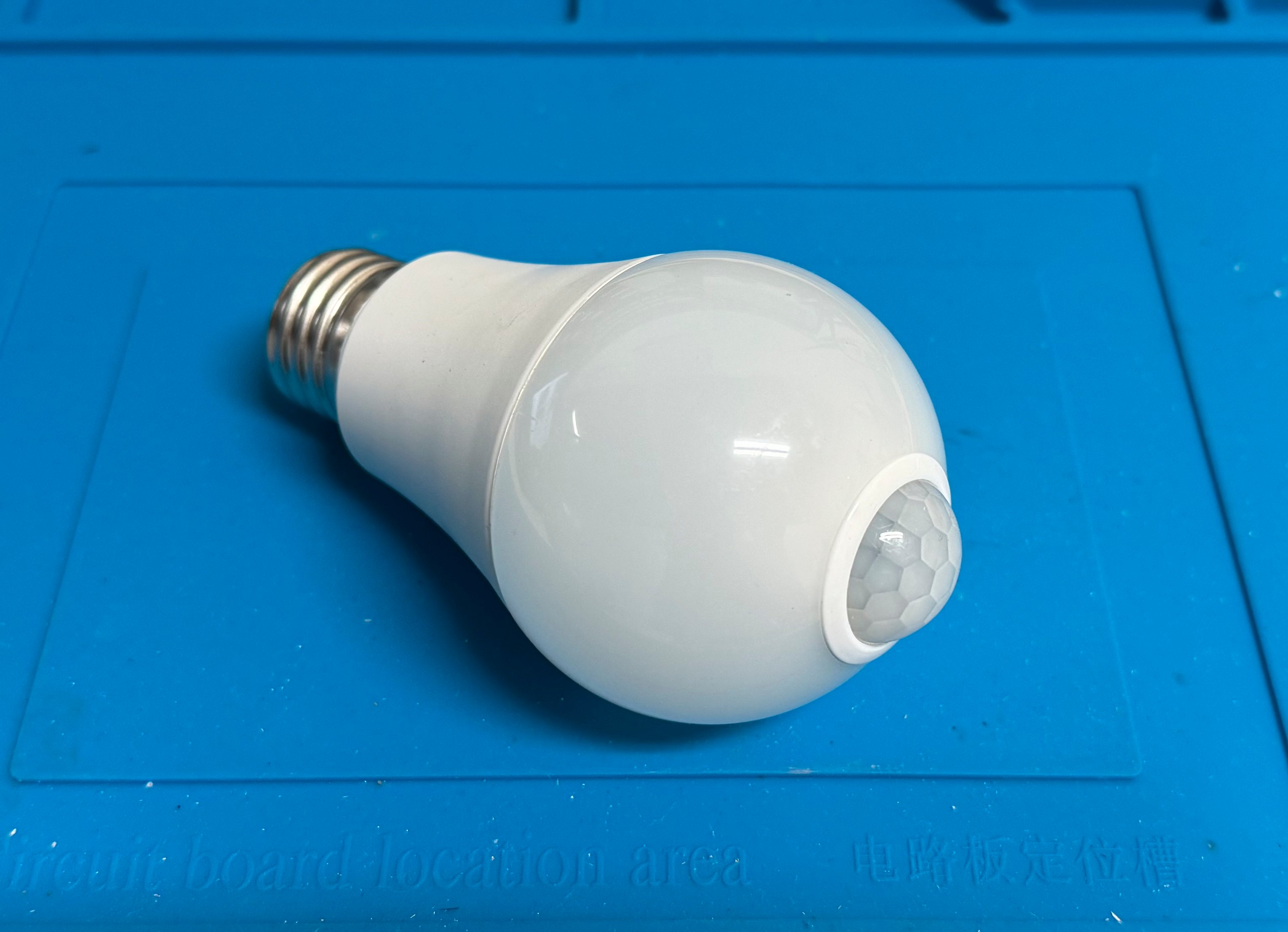
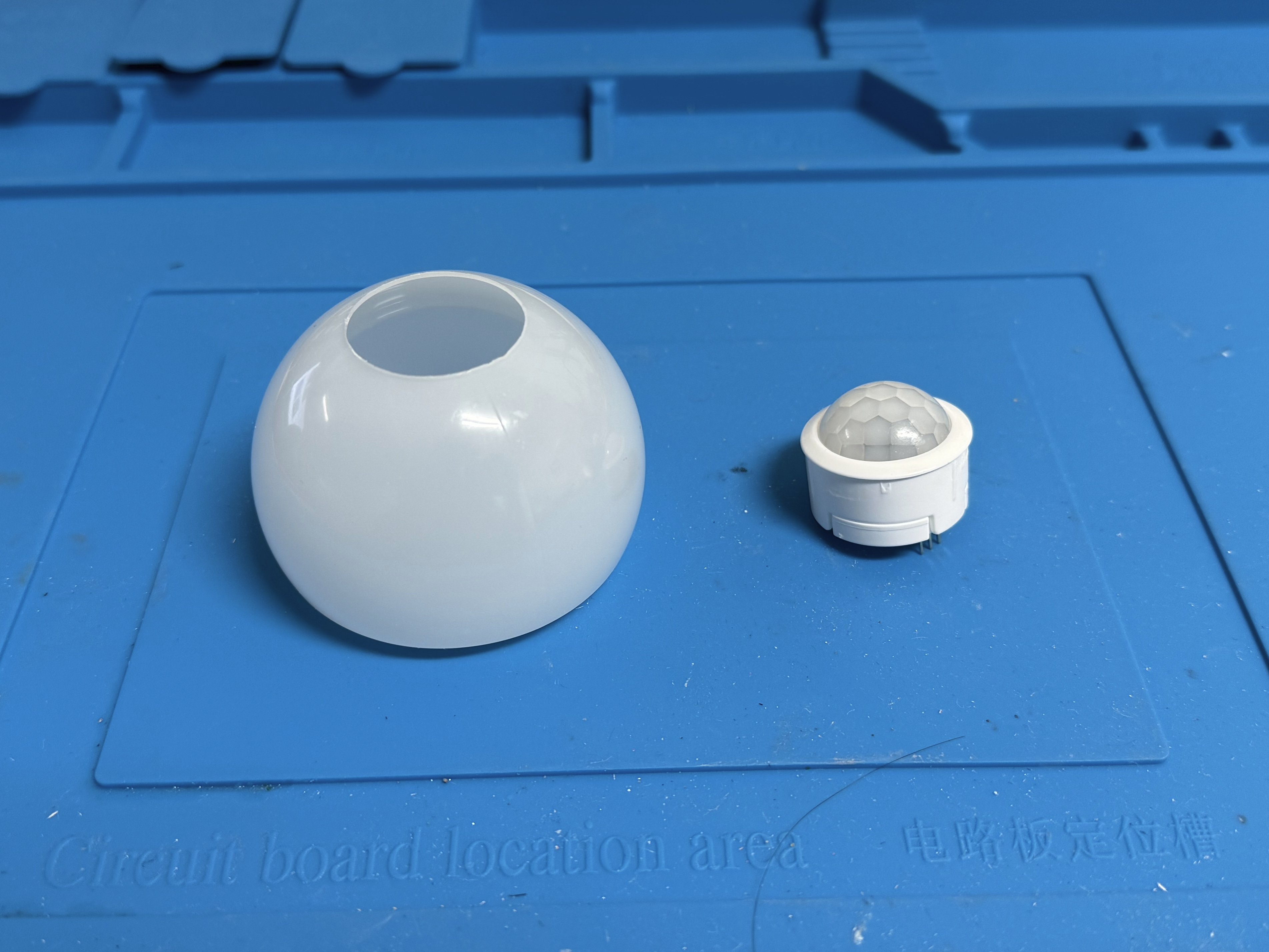
The bulbs are your standard screw-in versions with a sensor module in the center. Opening the bulbs up is pretty straightforward, I just had to loosen the adhesive connecting the round bulb to the LED assembly and pry it open with a knife.
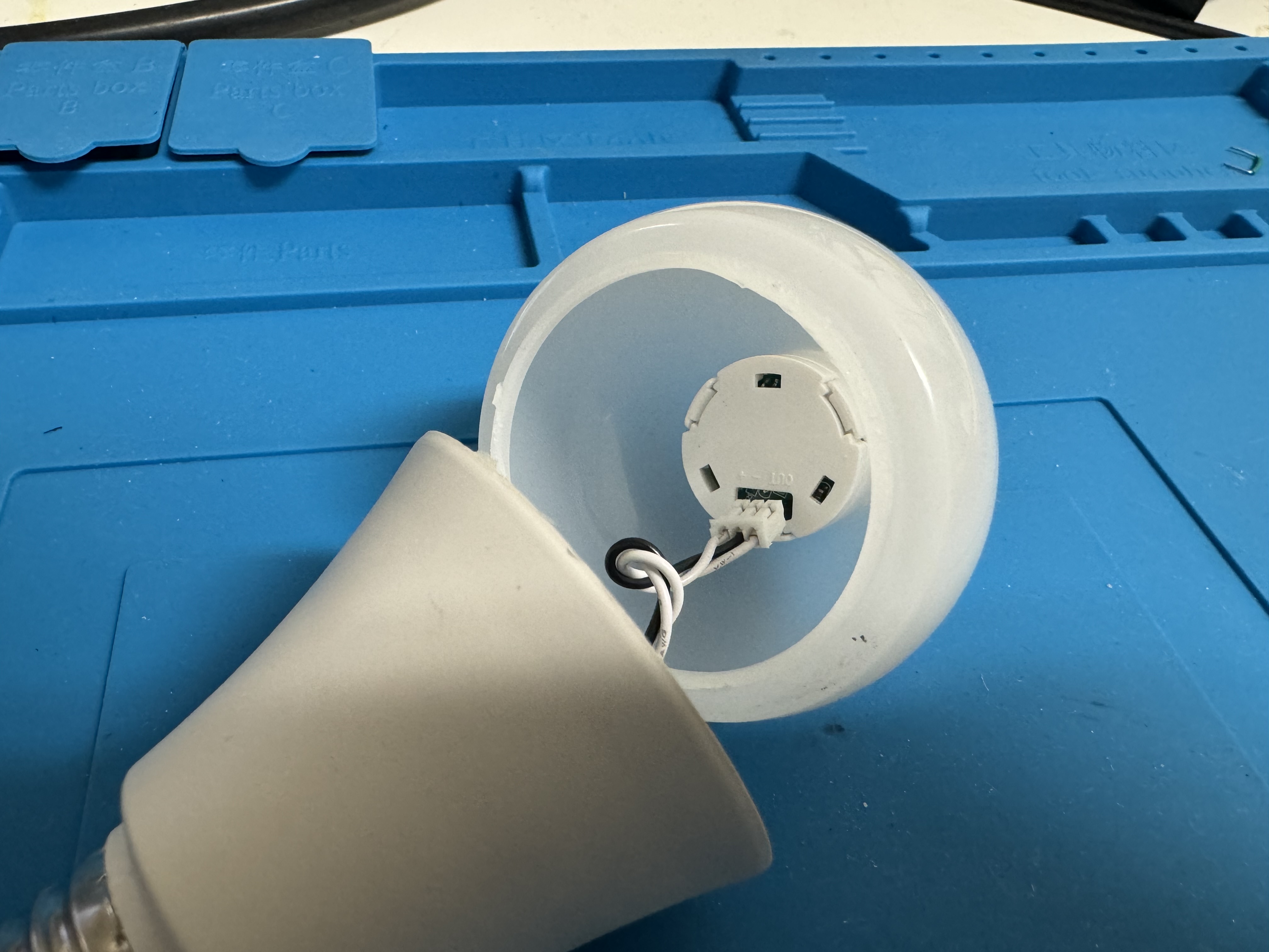
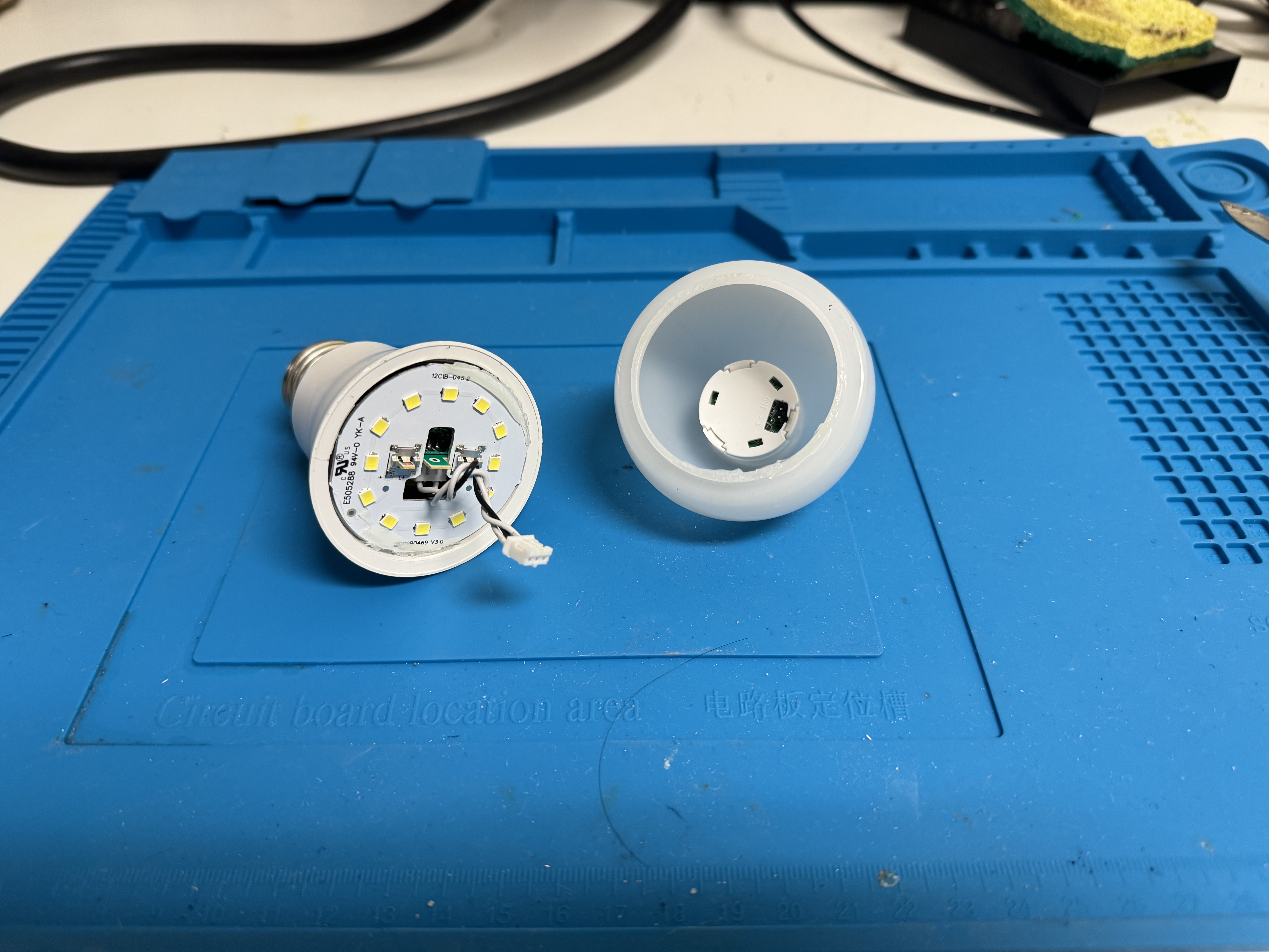
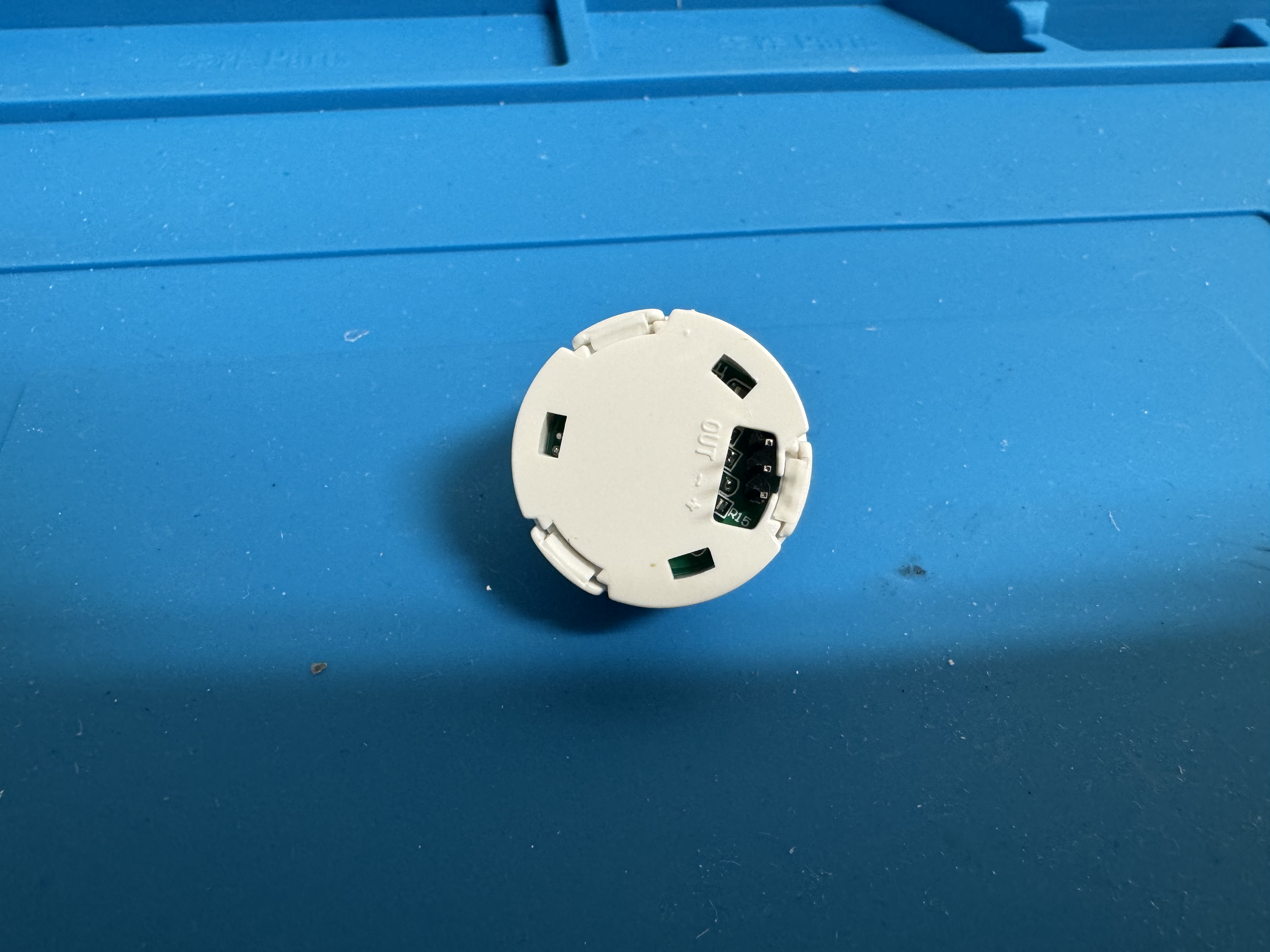
The inside has a aluminum PCB for the LEDs and their drivers and a 3-pin wire connecting the driver to the PIR sensor. At this point I was pretty certain that these pins were Power, Ground, and Sense, where a specific state on the Sense pin turned on the LEDs.
The Sensor Module
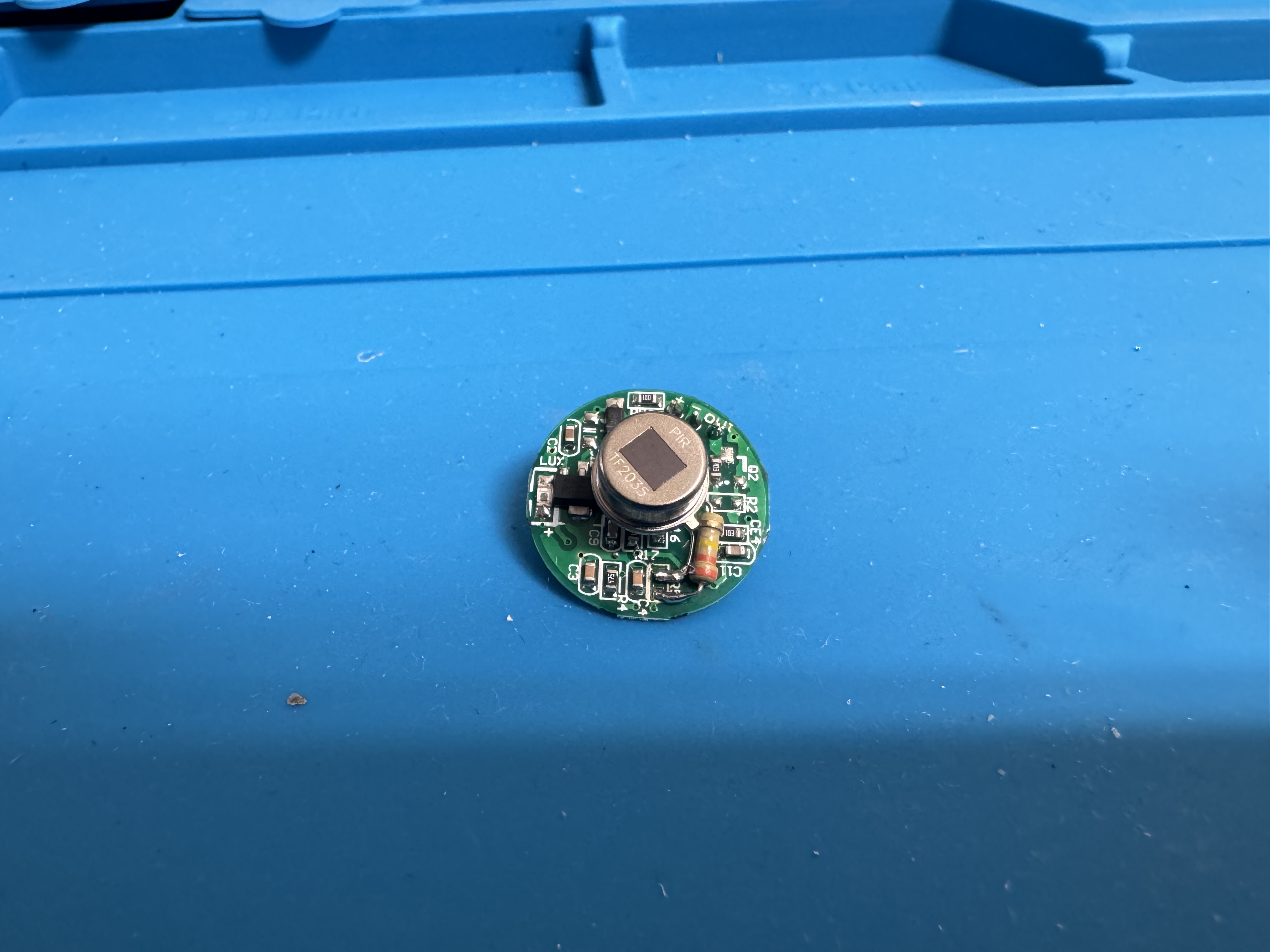
By looking at the sensor module it is clearly a PIR motion sensor.
How a PIR Sensor Works
A PIR (Passive Infrared) sensor is one of the most common motion detection sensors. Unlike active sensors (like ultrasonic or LiDAR), the PIR sensor “looks” for changes in IR light. The sensor has two sensing areas within. When there is no motion, the IR signature is constant. However when something moves within its view, one sensing area will have a signature different from the other. This behavior is used to trigger the sensor.
The coolest thing about these sensors is the lens. Most PIR sensors (including this one) use a Fresnel lens (the white dome on top). Fresnel lenses are used in lighthouses to create a beam of visible light from an isotropic light source. Similarly, the PIR sensor uses the lens to focus IR light from a wide angle onto the sensor area.
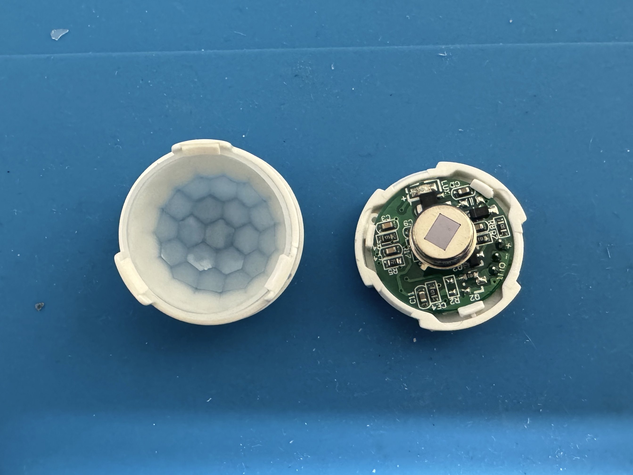
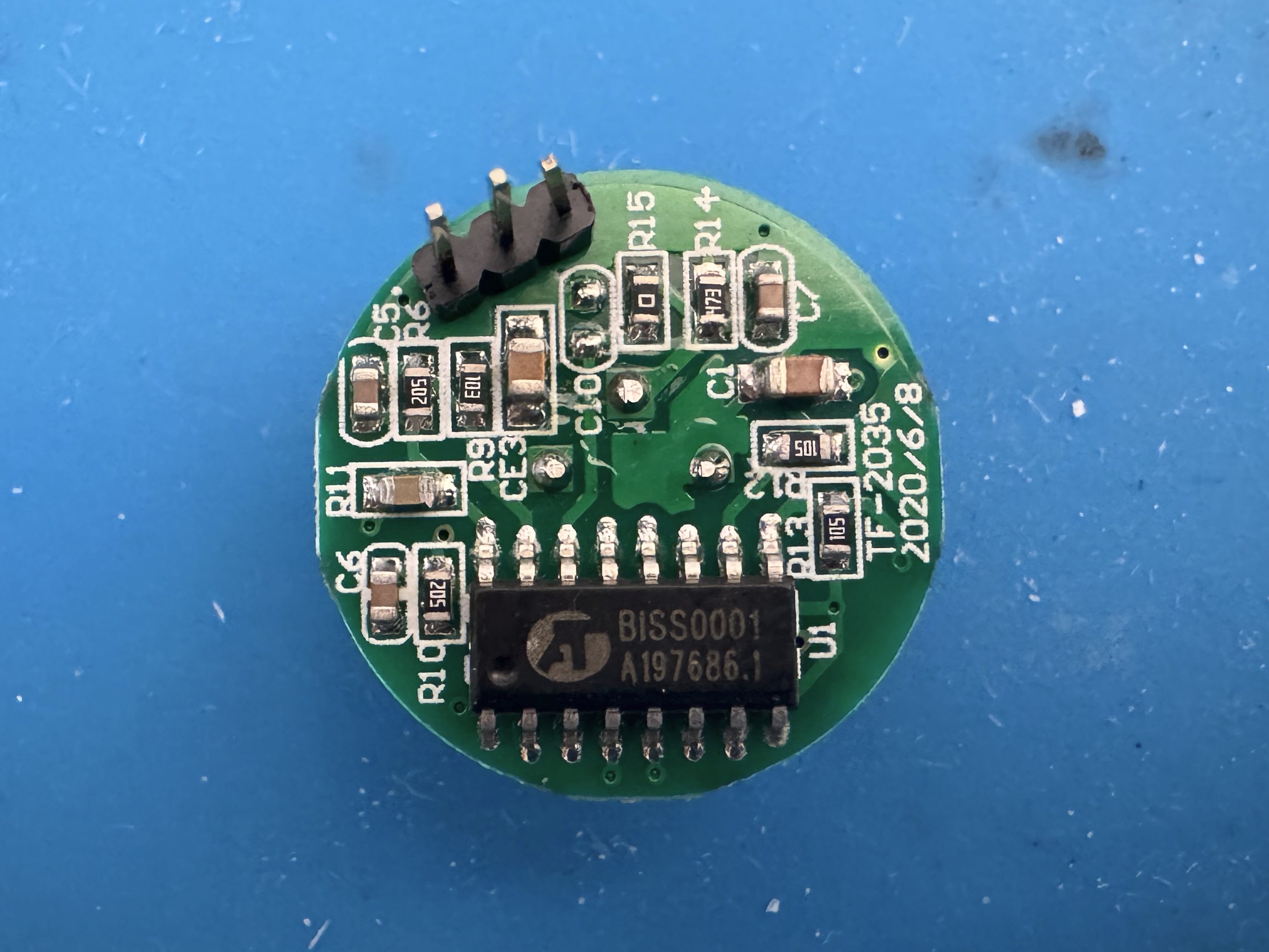
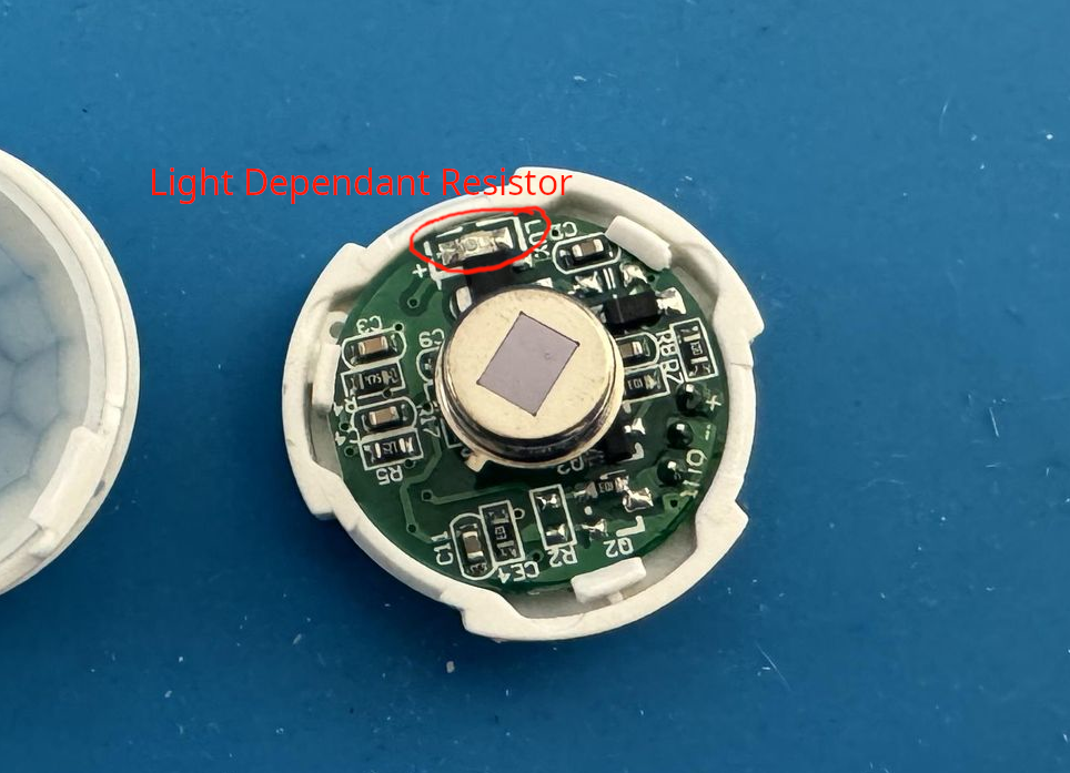
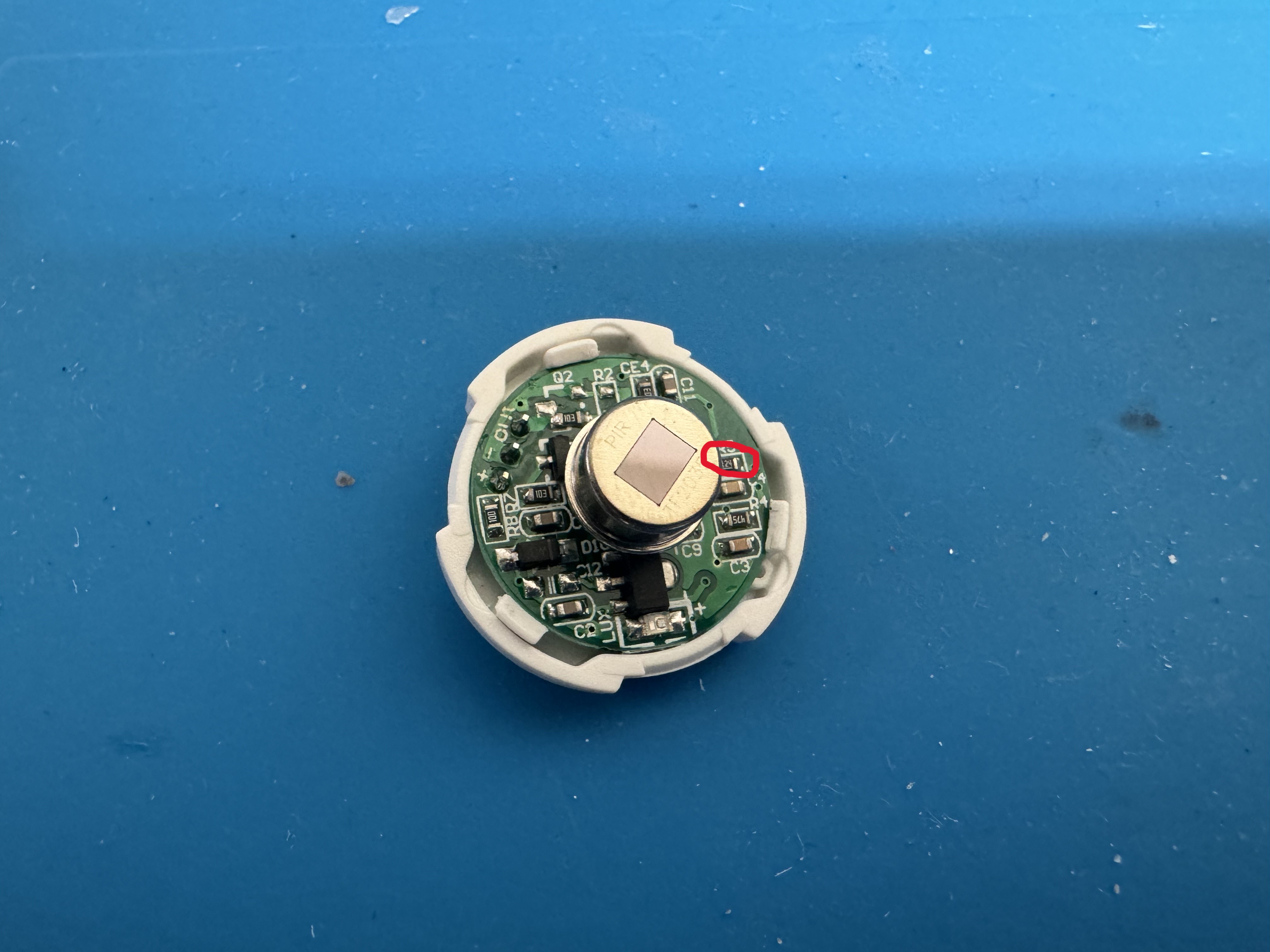
After removing the Fresnel lens, we can see the bare PIR module. There are also several other components, including a voltage regulator, what appears to be a LED, and a BISS0001 chip.
Understanding the BISS0001
The BISS0001 is a cheap IC for PIR sensors. Those who have used this chip in the past may recognize them from the common PIR modules you get with Arduino sensor kits.
Pulling up the BISS0001 datasheet yields a ton of useful information. The chip has three main controllable settings:
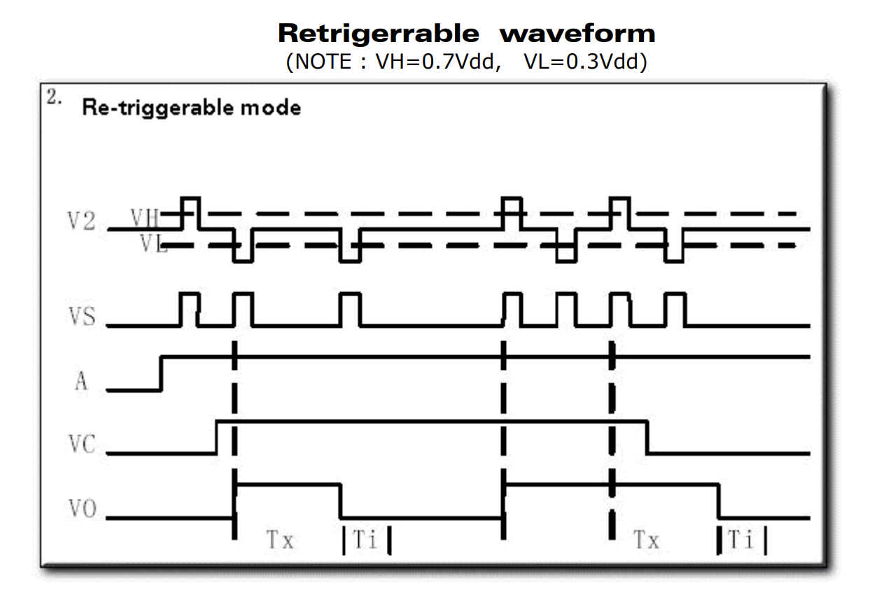
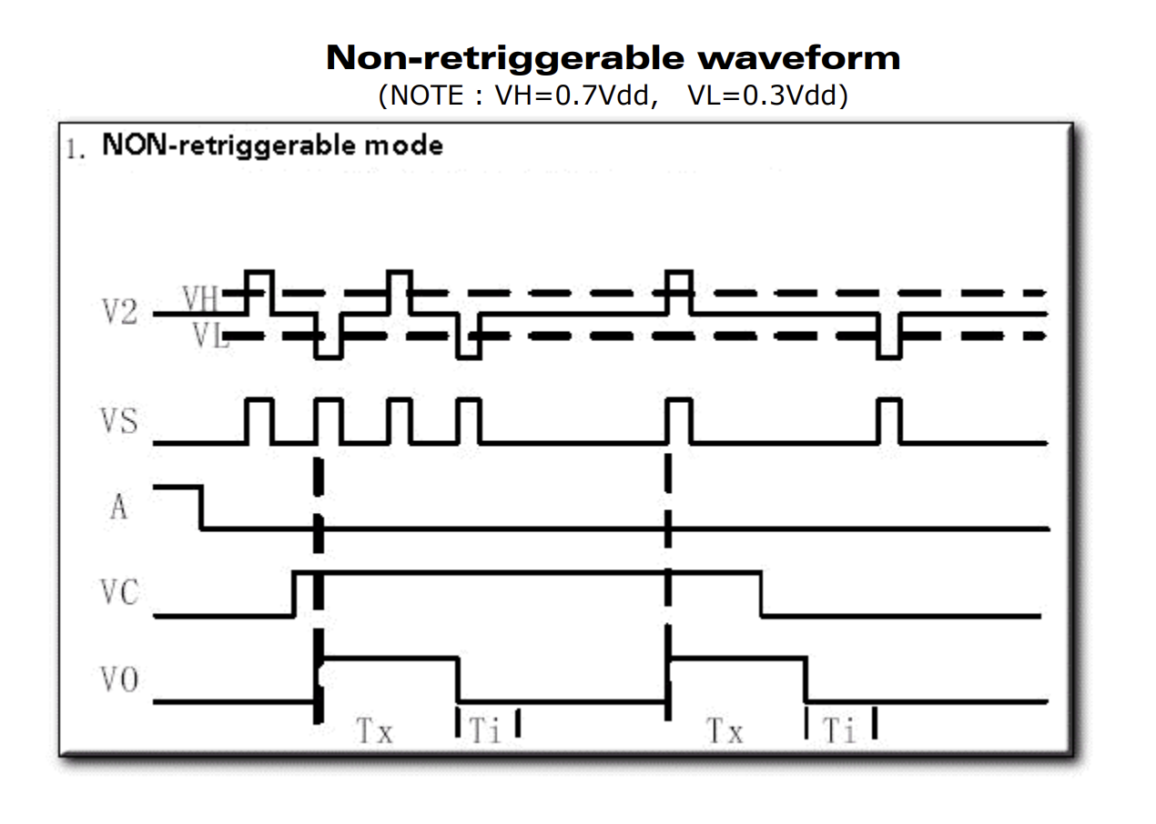
- Retriggerable and Non-retriggerable mode: Setting pin 1 high puts the sensor in retriggerable mode. This means that once motion is detected and as long as the output pulse timer has not expired, repeated motion will hold the output high. Likewise, holding pin 1 low means that the output will turn off exactly when the output pulse timer expires.
- Output pulse width control: By using a specific resistor/capacitor value on pins 3 and 4, the output pulse width, or how long the output stays on, can be controlled.
- Trigger inhibit control: Similar to the pulse width, a resistor and capacitor can be used to control the trigger inhibit time. During this time period, any additional motion will not trigger the sensor. This is used to prevent false positives and acts as a debouncer for the sensor.
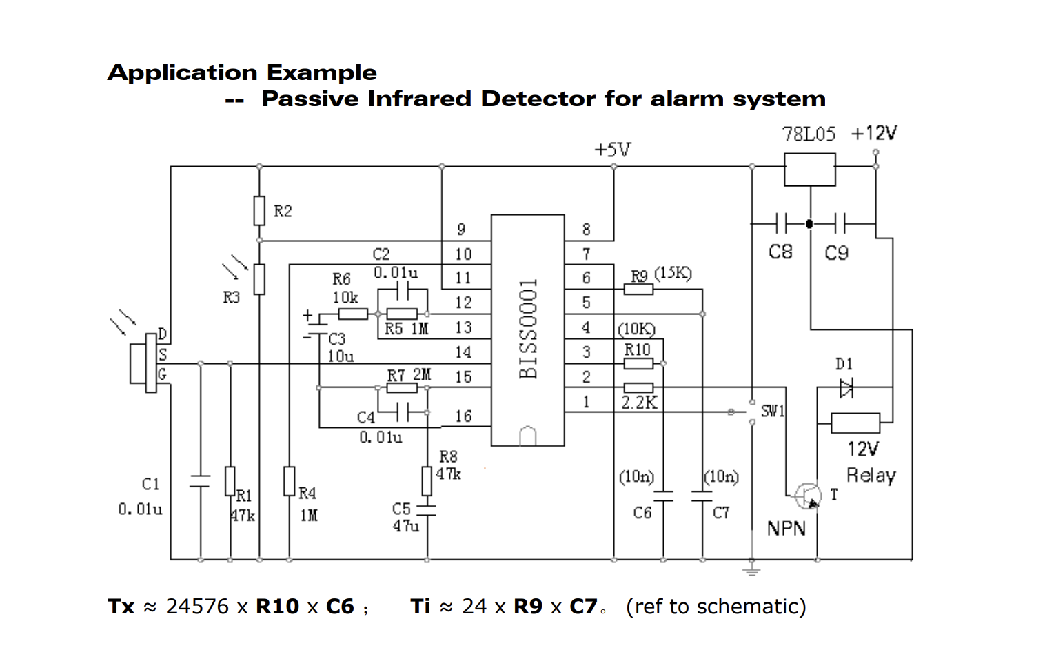
Looking at the sensor PCB, it is notoriously similar to the datasheet’s example schematic. Nevertheless, I traced as many components as possible to determine the actual schematic. There were a few variations in component values, but it was nearly identical. One interesting thing I saw was that a footprint for a transistor was used for a resistor, weird!
It turns out that that LED I saw earlier was in fact a LDR (Light Dependant Resistor). This is a nifty feature that only allows the sensor to trigger in night/low-light conditions.
The Schematic
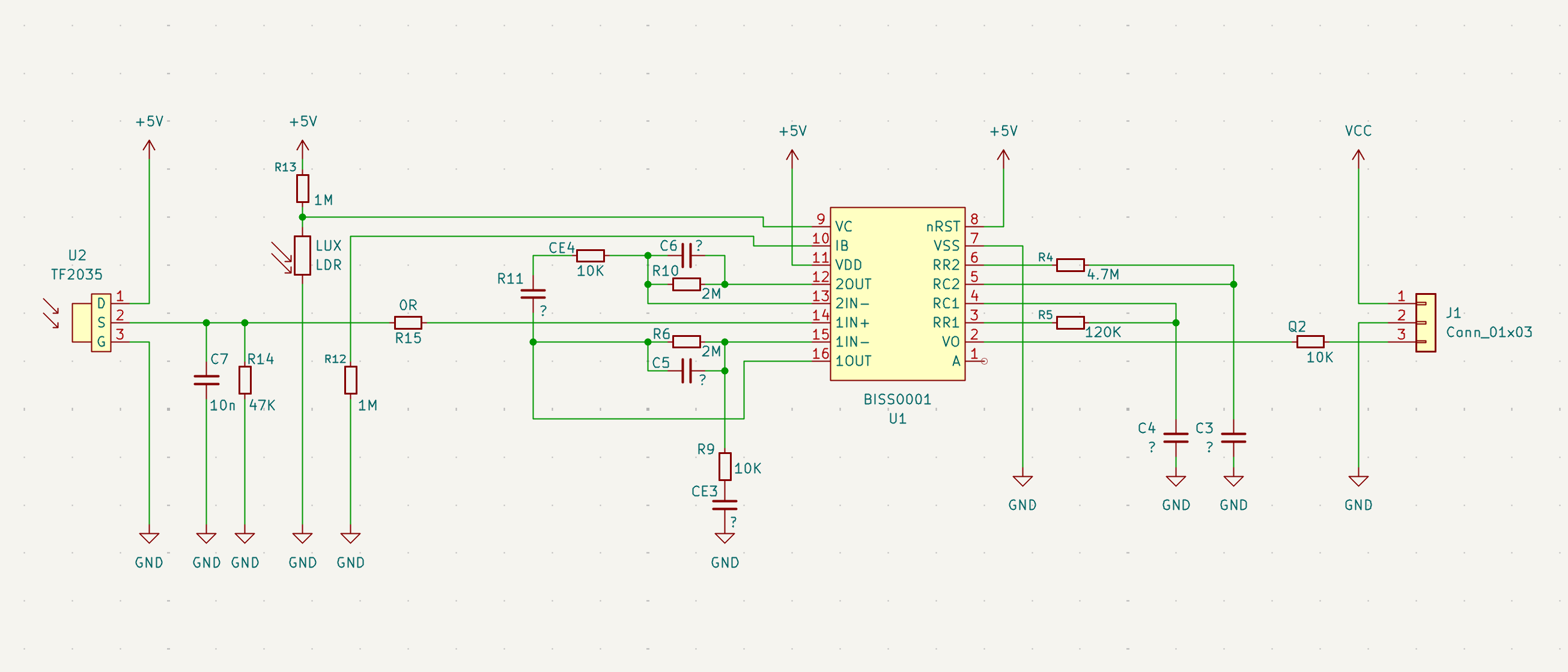
This was the schematic I reverse engineered. It is near identical to the datasheet’s application example. Note that this schematic does not contain every component on the PCB such as protection and voltage regulation circuits. I have used the component names as they are silkscreened on the PCB. Any unknown component values are substituted with a “?” (but they are probably equal to the application example’s values).
Some more weirdnesses I found were that a resistor and capacitor had their silkscreens mixed up. To ensure consistency I followed the PCB silk exactly as it was made (which is why CE4 is a resistor while R11 is a capacitor!).
How the BISS0001 Works
The BISS0001 has a 3-stage analog frontend to condition the incredibly small PIR signal into a usable voltage. This output is passed into a digital status control block which controls the true sensor output.
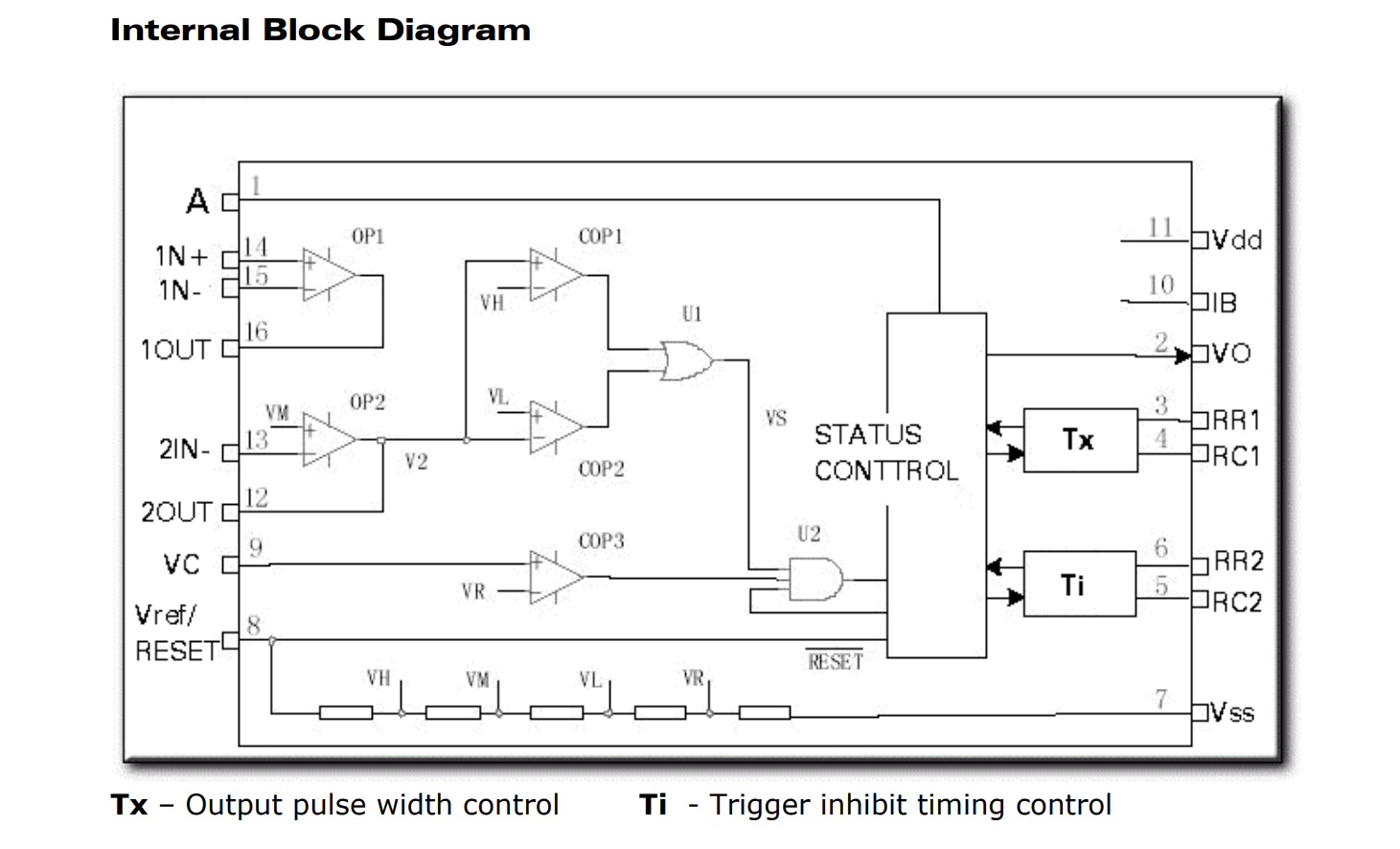
Looking at the internal block diagram we can see several interesting circuits. The various voltages needed for the op-amps and comparators are made using a string of resistors. The circuit also includes ambient light control and configurable trigger/output times.
To make this schematic easier to understand I recreated the internal block diagram using discrete components, including the external resistors and capacitors. I’ve placed the relavant pin numbers on their corresponding nodes. for simplicity I have removed the status control block and resistor string.
Note: Any calculations involving unknown component values (parts marked with “?”) will use the assumed component values from the example schematic.
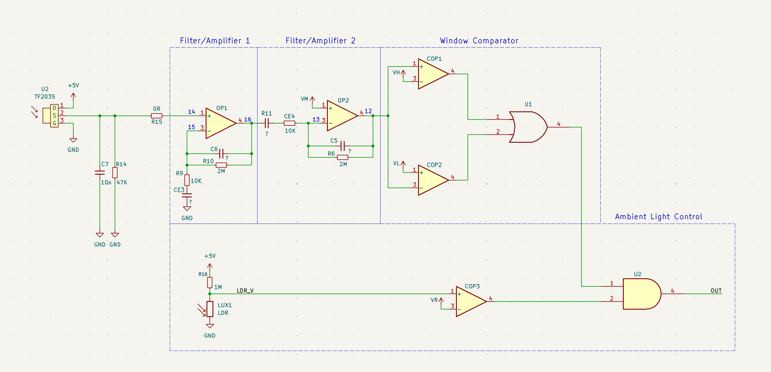
Filter/Amplifier 1
This first stage contains 2 filters. The first is a low pass filter using R10 and C6. We can determine the cutoff frequency using the formula:
Components R9 and CE3 act as a high pass filter removing the DC component of the signal. Its cutoff frequency is:
The gain from the op amp OP1 is equal to:
Given the low-frequency nature of sensing motion, the band of 3.4-8.0Hz is plenty.
Filter/Amplifier 2
The second stage is nearly identical to the first stage. The main difference is that its noninverting input is fed from the aforementioned resistor divider string. Both stages work in tandem to filter and amplify the weak PIR signal.
Why Two Stages?
So why 2 distinct filter/amplifier stages over a single large stage? One reason is signal stability. Op amps with very large gains may have poor phase margin, while splitting the amplifier makes it much easier to compensate.
Another critical reason is improving the filtering response. By cascading stages the overall frequency response is far sharper than only using 1 stage. This helps with rejecting DC drift, temperature changes, and other noise (such as 60Hz mains frequency).
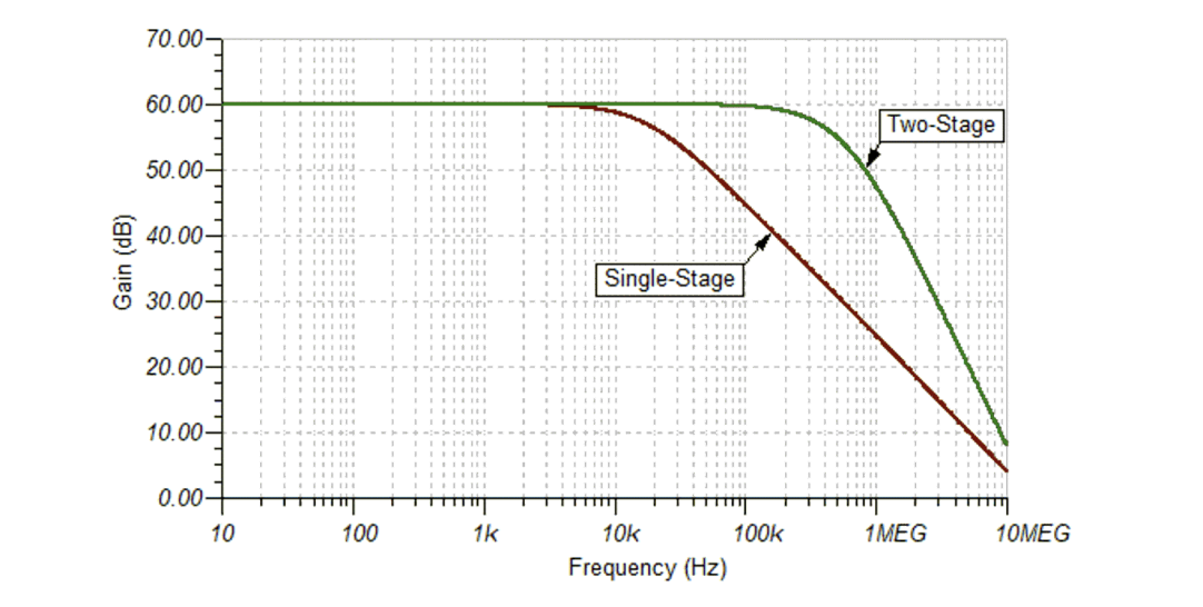
Using 2 op amps also prevents saturation. PIR sensors often deal with large, slowly changing factors such as temperature and sunlight. Having a single stage with a large gain could cause the amplifier to clip. With two stages, the first stage removes most of the low frequency noise before the second stage applies further gain.
Window Comparator
This is where we begin to leave analog land and start to go digital. Two comparators work together to output a high signal when either the analog voltage drops below or above predefined thresholds (from the resistor string). This is fed into an OR gate to supply a clean HIGH/LOW signal when the sensor is triggered.
Ambient Light Control
Before the signal enters the status control stage, it is gated by the ambient light in the room. A simple LDR voltage divider fed into a comparator is AND’d with the output signal. This ensures that the sensor can only trigger the lights when it is dark outside!
Configuring the Sensor
Now that we know how the PIR sensor and BISS0001 works, we can figure out how to configure the sensor to extend its on-time.
Trigger Mode
The sensor can be set to “retriggerable” or “nonretriggerable” mode by setting the “A” pin HIGH or LOW. With the sensor in “retriggerable” mode, the output pulse timer is reset every time motion is detected. When not in this mode, the sensor needs to be retriggered again (after the trigger-inhibit time Ti) to activate.
Output Pulse Width
To extend the on-time of this sensor, we need to increase Tx (output pulse width). The datasheet and schematic show that this value is a function of R10 and C6 (R5 and C4 in our schematic). It is given by this formula:
We already know the value of R5, but what is C4? Unfortunately I dont have an LCR meter in my garage, so we will have to find it by elimination.
By triggering the sensor and measuring the pulse time with a stopwatch, we can determine the current Tx value. Then we can solve for C4. Reassembling the sensor and hooking the output to an oscilloscope, I measured the current on-time to be 38 seconds. Solving for C4:
Now we can recalculate the resistance for our new on-time. I want the light to remain on for ~100 seconds. Solving for this:
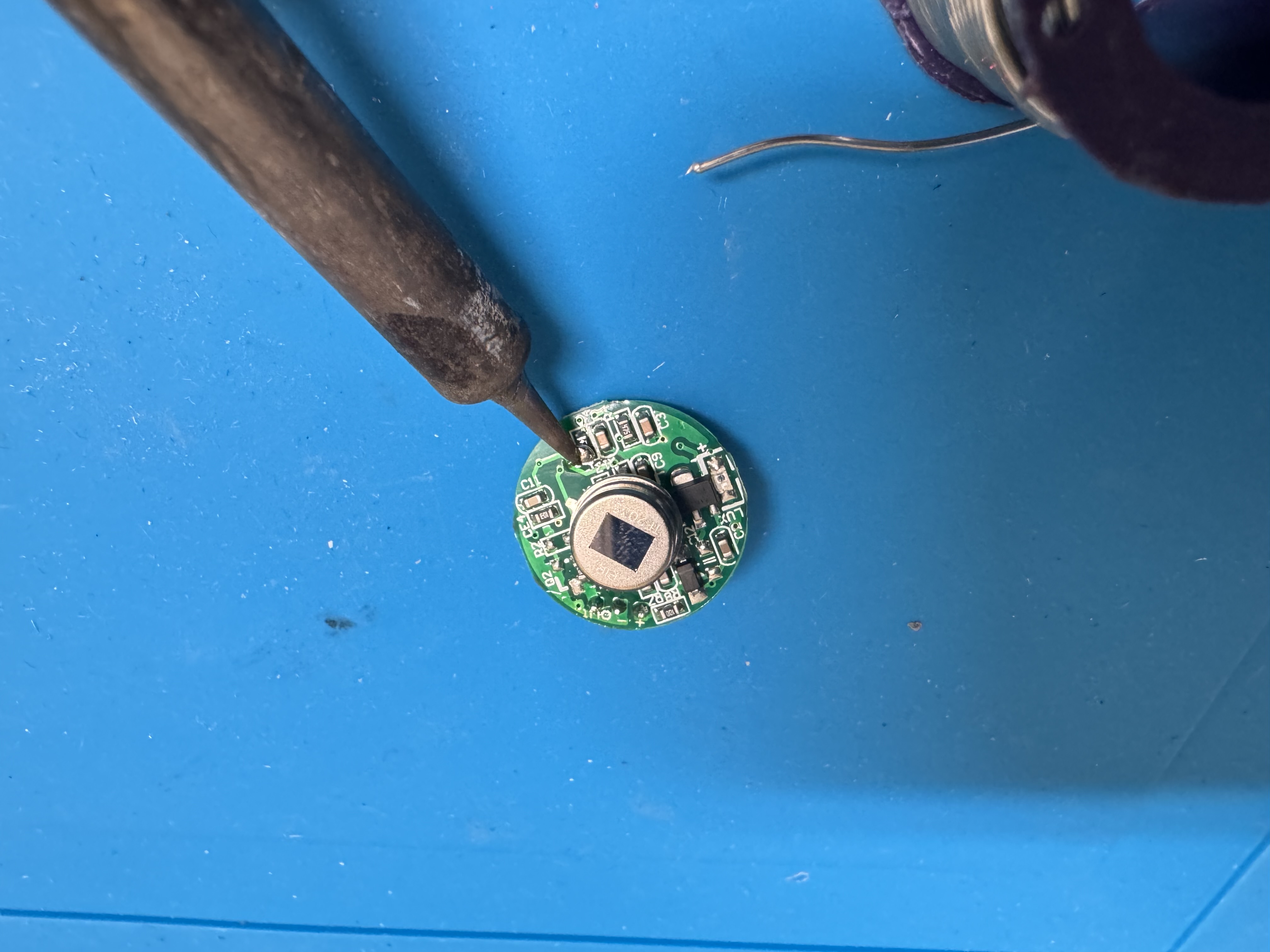
I chose a 330K resistor as it was available. Now its just a matter of removing the old resistor and putting in the new one! Ideally this should be a SMD part, but I only had a THT of that value. Not my best work here.
Trigger Inhibit
This process is nearly the same as the output pulse width. Its formula (already adjusted to my schematic) is:
This one will be a bit more difficult to track as you need to time how long it takes between the sensor turning off and coming back on again, all while moving in front of the sensor.
Conclusion
At this point it was time to test my connections, reassemble the device, and reinstall!
With this single resistor change I was able to extend the on-time to over 100 seconds (more than enough time to get my bins out of the yard). Its pretty incredible how something so simple has so much built into it. I hope this deep dive is useful for anyone curious about these sensors!
Note: For additional build instructions, please see my Instructable.